

BASIC INTRODUCTION TO ULTRASONICS
Ultrasonic testing (UT) has been used as an NDT method for a number of years in general industry and there is still a fair amount of confusion regarding the capabilities and the terminologies of this method of testing. The intention of this article is to provide a better understanding of the “dark art” of ultrasonic testing to the “non-NDT” fraternity.
AN “EXTREMELY” BRIEF INTRODUCTION TO UT
Ultrasonic Testing as an NDT method was created as a “by-product” of the development of radar technology during 1940’s and became used in the industrial sector in the mid 1950’s. The ultrasonic wave is generated into a part by using the “piezo-electric effect” whereby an electrical pulse is placed on a crystal (e.g. Barium Titanate), this crystal vibrates creating a mechanical stress wave into the item being tested, once the stress wave strikes an interface i.e. a back wall or a discontinuity, it is reflected back to the crystal where the wave is, once again, converted back to an electrical signal which is converted through a Cathode ray tube (or more recently, through a digitizer) into a signal on the Ultrasonic flaw detector screen.
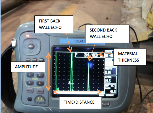
The standard test technique utilized in general industry uses an A-Scan display which provides information as to the time/ distance and echo amplitude (relative size) of an echo. Conventional UT testing uses two wave mode forms i.e. longitudinal/compression wave (normally used for thickness testing and shear/transverse wave (used for weld scanning with numerous probe angles).
The UT method is an invaluable testing method which has been successfully used for many years in the power generation, petrochemical, mining and fabrication industries and technologies are improving all the time.
MIMIMUM SIZE FLAW CAPABLE OF BEING DETECTED BY THE ULTRASONIC METHOD
The ultrasonic testing method is capable of detecting flaws with a minimum through thickness dimension of ½ λ (λ = frequency/material ultrasonic velocity), in steel this is approximately 0.48 mm.
DETECTION AND EVALUATION OF ULTRASONIC SCREEN SIGNALS
Prior to commencing any ultrasonic test the UT practitioner will calibrate the flaw detector to the desired time/distance required using standard calibration blocks and set the flaw detector sensitivity (gain) using reference blocks, in general industry a block with a set of 3mm side drilled holes at different depths is used to provide a Distance Amplitude Correction (DAC) curve. The DAC curve is used to offset the attenuation (loss of sound energy) as the ultrasonic wave travels through the material.
ULTRASONIC TESTING VERSUS RADIOGRAPHY
Unlike Radiography, where an image is provided on a film, UT requires the skill and the knowledge of the practitioner in determining the type of flaw detected depending on the display. Acceptance criteria is generally determined by the length, echo dynamic pattern and the echo amplitude of flaw indications.
Radiography is a versatile NDT method capable of detecting most volumetric flaws i.e. porosity, slag etc. UT, on the other hand is a far more preferable method for detecting specular (mirror-like) flaws i.e. cracks, lack of fusion, incomplete penetration etc.
It must be emphasised that no NDT method is perfect for detecting all types of flaws and it is up to the NDT specialist, e.g. the Level Three, to determine the best method suitable for the application.
ECHO DYNAMIC PATTERNS OF FLAW INDICATIONS
In general, the interpretation and evaluation of UT flaw indications is primarily based on the echo dynamic pattern of an indication. The pattern is determined by the “envelope” created by moving the ultrasonic transducer over the flaw indication in a “to and fro” motion.
Pattern 1 indications are typical of isolated gas pores, over penetration, root concavity etc.
Pattern 2 indications are typical of lack of fusion, incomplete penetration etc.
Pattern 3 indications have “jagged” pattern envelope which may be typical of cracks or slag inclusions, this requires a higher skill level in evaluating.
Pattern 4 indications are multiple pattern 1 indications, and are typical of cluster porosity.
MOST COMMONLY MISUNDERSTOOD TERMINOLOGY USED BY UT PRACTITIONERS
SHORT RANGE SIGNAL – When conducting a “critical root scan” of a component it is essential to be able to focus in the root area, The practitioner does this by placing the UT probe at the calculated distance from the weld centreline and “interrogating” the root area, this serves to assist in determining if signals detected are from normal root profile or from actual root flaws. This process is the most time consuming but also the most important aspect of any ultrasonic test.

BACK WALL ECHO – A back wall echo is the signal received from the inner surface of the item.
BEAM PATH LENGTH (BPL) – The beam path length is the distance from the probe to an interface, in order to calibrate the system to be able to fully inspect an item the BPL must be calculated by using the formula BPL = COSΘ/2t where; Θ is the probe angle and t is the thickness of the material.
MODE CONVERSION – This is one of the most commonly misunderstood terms, by practitioners and others. A Mode conversion occurs when a wave strikes an interface and a “secondary” wave is reflected which is in a different wave mode form i.e. a compression wave converts to a shear wave or vice versa. The important thing to remember is that mode conversion will only take place after the initial sound wave strikes an interface.
Gordon McGarrie